
 English
  English
Views: 370 Author: Site Editor Publish Time: 2019-03-28 Origin: Site
Introduction:
The installation of this solar collector should only be performed by personnel qualified in plumbing and roofing. The installation should comply with local building codes, permits and requirements. The collector installation can be retrofitted to existing buildings or integrated into new construction projects.
Theory of Operation
A solar collector is simply a heat exchanger designed to convert the suns radiant light energy into thermal energy to be stored for later use. This collector uses non-imaging optics and parabolic concentration technology to heat the fluid media passing through the selectively coated tubing manifold. The fluid media is circulated, via a pump, through the collector and into a storage tank located within the home/building.
Collector Orientation
The performance of solar collector is optimized when the collector is mounted facing true south. Performance, however, suffers very little when the collector is oriented no more than 45° East or West of True South. The collector should be un-shaded by any permanent obstacle between 9:00 a.m. and 3:00 p.m. on any day of the year.
Collector Tilt
Optimal annual efficiency is achieved by tilting the solar collector at an angle that equals your latitude plus an additional 10°. This tilt angle favors the lower winter sun when collector performance is at its lowest and minimizes overheating during the hottest summer months.
The solar collectors in a two collector staggered mount installation must be spaced far enough apart to prevent winter shading. Table 1 and Figure 1 show the correct spacing between collectors to prevent shading on December 21, when the sun is at its lowest angle. So as the collector distance to the walls , to be sure that there would be no shade on the collector all the year round .

figure 1
Basic Mounting Procedures
Freeze protection is strongly recommended; therefore, the collector should always be mounted in a vertical orientation.
The solar collector should be mounted on the roof in accordance with these general principles:
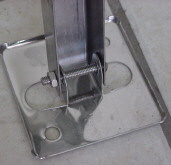
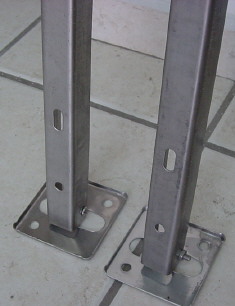
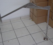
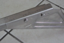
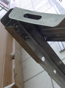
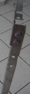
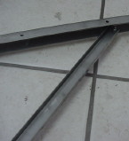
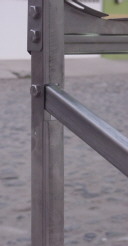
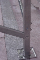
There is a stand parts which should be assembled on the roof together with the whole system, it is not suggested to assemble the system in area which has very heavy snow and hurricane often. The most important structural consideration is to securely anchor the solar collector and the mounting hardware to the structural members of the roof with stainless steel hanger or lag bolts.
If the region is subject to high wind or hurricane conditions, additional steps may be required to secure the collector and mounting hardware to the structural members. In certain areas of the country, local building codes may require collector wind load testing or prescribe specific mounting procedures. Consult your local building department.
Collector Plumbing
This installation requires the use of all copper and brass fittings in the collector loop plumbing. Couplings rather than unions should be used to join the collectors to avoid leaks and fluid loss. Use only lead-free solder. Use of 50/50 lead solder is expressly prohibited. Use of galvanized steel, CPVC, PVC, or any other type of plastic pipe is prohibited. The minimum size for the To and From collector piping is 5/8 OD copper. Copper plumbers tape or tube strap is required. The pipe insulation may not be compressed or crimped by the strapping Material.
This solar collector is leak tested at the factory. Once the collector has been installed as part of a domestic solar water heating system, the system should be filled, pressurized and checked for leaks. Repairs should be corrected and the system retested prior to insulation installation.
Pipe Flashings:
Pipe flashings are used to transition through the roof membrane and into the attic space for
subsequent connection to the interconnect
plumbing. All roof penetrations are to be sealed in accordance with standard roofing practices. Make roof penetrations between trusses to allow for thermal expansion and slight flexing of the pipe from wind buffering.
Standard plumbing roof vent stack flashings can be used, however, the rubber or plastic boot must be protected from the sun. Figure 12 details an all copper flashing which uses a coolie cap soldered to the interconnect plumbing. This connection should be made prior to insertion through the flashing base.
Piping in new solar installations can be covered with dirt, grease, solder flux or other impurities that over time affect the quality of the distilled water or propylene glycol heat
Technical data:
SPP-470-H58/1800-18-C includes water tank, reflector, heat pipes and structural supporting marks.
18 heat pipe collector. SC tube with copper pipe and aluminium fin in it. The transfer fluid in copper pipe is 99% pure water and 1% acetone. Thickness of tube is 1.6mm. Diameter is 58mm. Length: 1800mm. copper thickness is 1.6mm.
Inner and outer tank: SUS 304 2B stainless steel. Inner tank thickness is 1.2mm. Diameter is 360mm. thickness of outer tank is 0.4mm. Diameter is 470mm.
Insulation: 55 mm of polyurethane foam to keep the heat with a capacity of 160 liters.
Electric power: 1500W-3000W
Hole dimensions: 1/2’’ or 3/4’’
Weight without water: 81kgs
Structural supporting marks/mounting: stainless steel
Reflector: aluminium
Maximum operating pressure: 6bars.
Maximum pressure: 8bars
Maximum teperatures: 95.C
Type of heat transfer fluid: Acetone
high pressure solar water heater series
Package:
The solar system consists in 4 boxes with the following components
Box 1: Stainless steel marks
Box 2: Stainless steel tank
Box 3: Stainless steel reflectors
Box 4: glass vacuum tubes
Installation guidelines:
Box 1: marks: Split the components for size order. There are right side and left side components
The components 1 have to be orientated with the 8 holes looking inside of the mark (to install the sun reflectors)
Quantity | Description | Component | Quantity | Description | Component |
2 | Bar | #1 | 2 | Bar | #7 |
2 | Bar | #2 | 1 | Base to fix the tubes | #8 |
4 | Base for the marks | #3 | 18 | Plastic base to fix the tubes | #9 |
2 | Tank supports | #4 | 1 | Plug | #10 |
2 | Bar | #5 | 18 | Black rings | #11 |
2 | Bar | #6 | 1 | Bolts and nuts |


Step 1.assembly the marks
Assembly component number 3 with the components number 1 and 2

B. Assembly component number 4 with components number 1 and 2
C: Assembly components number 5 and 6 with the components 1 and 2
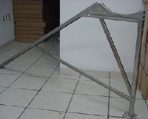

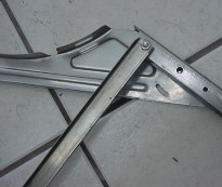
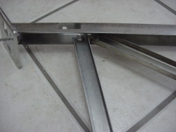
D: Assembly components 7 and components 2
E: Assembly component 8 and components 1


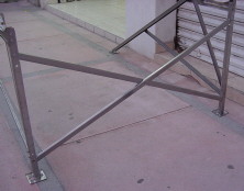
Step 2. Install the reflecting components

Use bolts sort 3
Step 3. Install the tanks into their supports


Step 4. Position of the system
Be sure that all the bolts are tightened and the system is totally rigid. Now you can orient the system. The best direction is south. Avoid shadows on the system.
Can resist the lowest temperature of -30℃
When the pressure reaches more than 6 bars, the P/T valve is open and release pressure.
The system requires a solid base, because the system weight is 241 when it’s full of water. Be sure that the system is horizontal. Fix the 4 bases of the system
Step 5. Collecting tubes installation
Take a tube out of the box carefully
Take out the tube. Apply the liquid silicon thermal paste on the top of the tube and into the hole into the tank
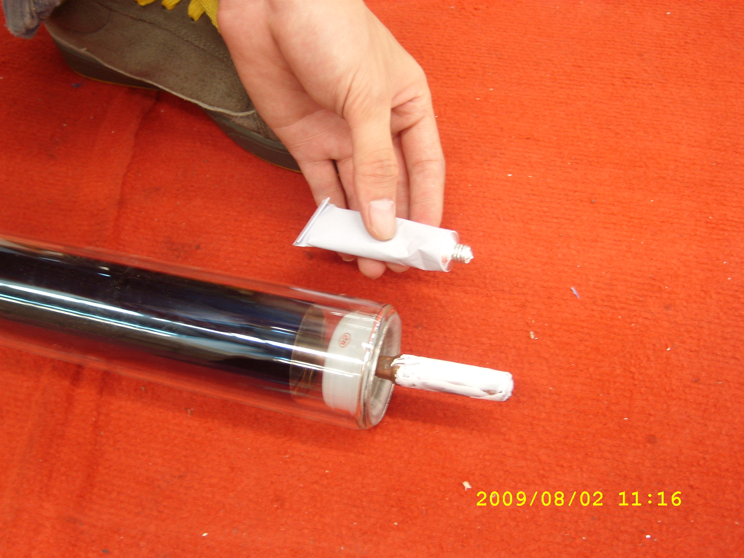
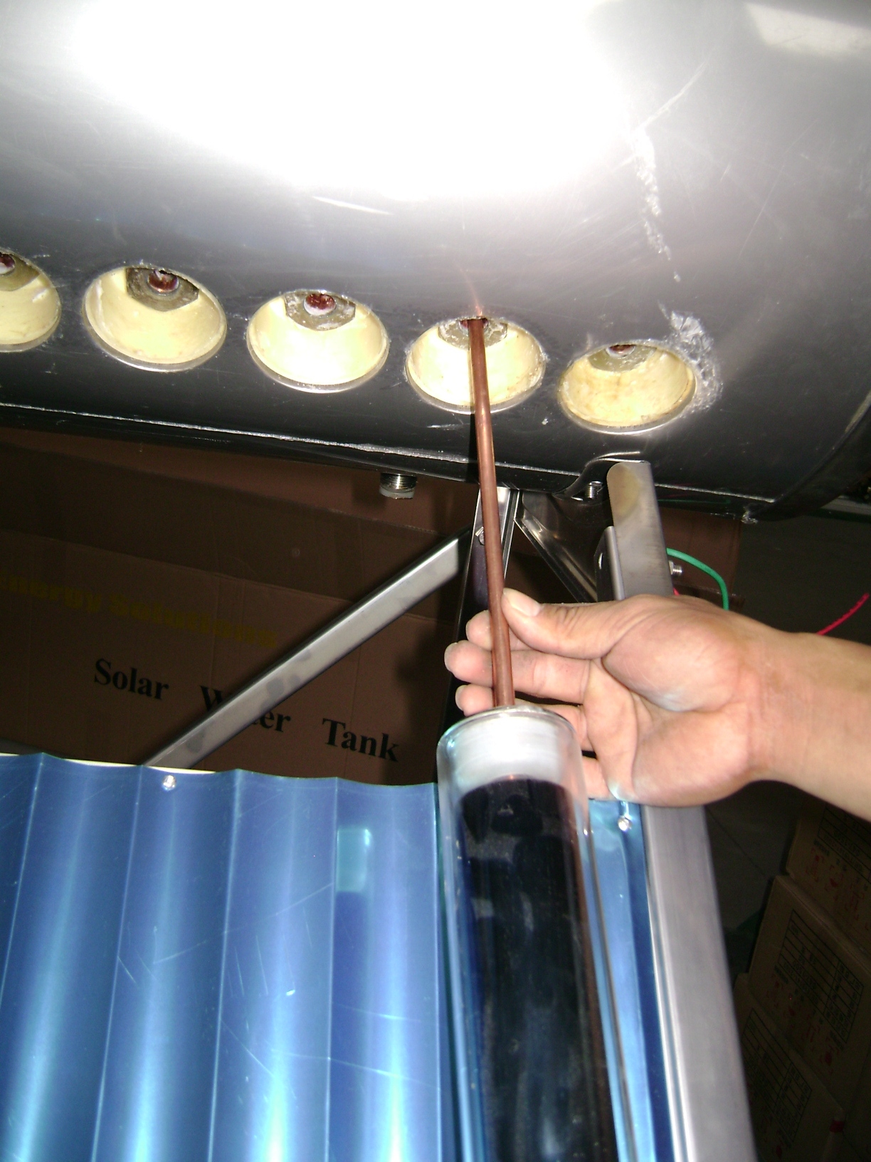

Insert carefully the tube into the hole of the tank and turn slowly in the watch direction, until the tube gets inside, and insert it turning into watch opposite direction until it gets strongly fixed into its base.
Move the black component to seal the tube with the tank
Put some Teflon at the tube where the hot water goes out (downside of the tank) and install the spherical key

P/T valve, when the pressure in the tank is more than 6 bars, the valve will open to release pressure.
Insulation pipe to protect frost.

Using controller

The function of the controller: 1.time display
2.temperature display
3. Temperature difference controlled circulation
4.hot water timing circulation at three preset time sections
5.time heating at three preset time sections
6.frost protection
7.memory protection when power is failure
8.trouble indication of sensor
Drawing of tank


P/T valve
e.
Electric backed hole
cold water in, hot water out
User guide
a). Existing safety and security components: P/T valve
b). Preceding to starting the system it all valves shall be checked for proper working and that the system is filled with water and antifreeze fluid completely.
In the event of any failure condition a specialist shall be called in.
c). Regular operation of safety valves:
d). Precautions with regard to the risk of frost damages and/or overheating
e). The manner of avoid failure when starting the system under frost or possible frost conditions:
f). Abandonment of system
g). Maintenance of the system by the specialist, including frequency of inspections and maintenance and a list of parts those need to be placed during normal maintenance
h). Performance data:
i).the system shall not be used in climate zones with higher irradiation values
j) the overheating protection: switch off electric power or fill cold water.
k). the system can resist the lowest temperature of -30℃
l). transfer fluid: acetone and pure water
m). type of transfer fluid: 99% pure water and 1% acetone.
Additional description
The products are subject to change without further explanation.


